
In this post I’ll go over my steps to get an STM32F4xx microcontroller running FreeRTOS as an SPI peripheral/device/slave using DMA so it can run in the background while the main task is running. There are a lot of examples online of setting up STM32 SPI controllers, but very few where it is used in slave mode, especially with DMA and integrating this with FreeRTOS. In particular, the main problem I found is that by default, all the interrupt handlers have the highest possible priority (priority 0), which means that you can’t call FreeRTOS API functions from inside them. This means, for example, that you can’t send a notification to wake a thread from the interrupt handler. The solution is to reduce the priority of the DMA interrupt handler to below the level the FreeRTOS handler is running, as described below.
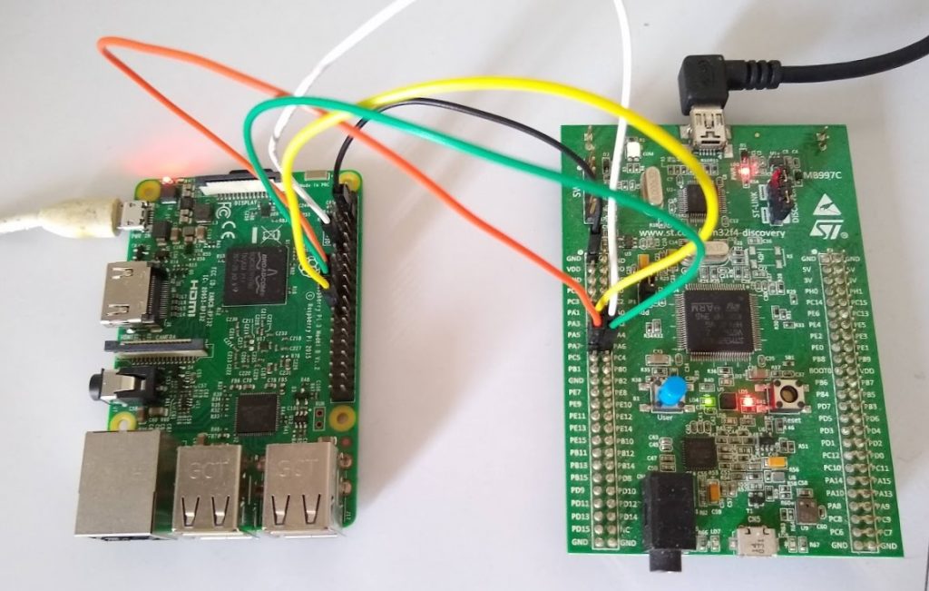
This post will focus on the SPI setup and configuration steps using STM32CubeMX, rather than the whole system design and communication protocol (that will be a future post). The final application will have a raspberry pi controller talking over as shared SPI bus to a number of STM32F412 devices, each running FreeRTOS. For the purposes of this post however, I will use a raspberry pi connected to a single STM32F4 discovery board (which has an STM32F407 MCU on it, which for the purposes of this post behaves identically).
I will be using STM32CubeMX to generate the code for the startup and system initialisation, as well as the HAL for the GPIO and the SPI/DMA peripherals. This tool actually seems to work reasonably well, especially for getting a project up and running quickly without having to read through all the documentation to even get the thing to start. It may not be optimised, but it is a decent starting point. The code it generates is scattered with start/end user code comment blocks. If you are careful put all of your own user code between these blocks, then you can freely go back and update the project in CubeMX and re-generate the outputs and it will keep all of your code, which makes it easy to change peripheral configurations and test the results.
The really nice part is that it can generate code compatible with GCC, including a startup and linker script, and a makefile. This is refreshing, as most other tools try to lock you in to one of the proprietary IDE/compiler ecosystems. (As a side note, this blog series https://vivonomicon.com/2018/04/02/bare-metal-stm32-programming-part-1-hello-arm/ has a really nice rundown of “bare metal” programming stm32 devices, starting from the startup script, linker, all the way up to compiling c code and running it)
I won’t go over the details of how to set up the build environment in this post, but here is the setup I use:
- GCC + make for building the binaries
- STM32cubeMX for initial setup/HAL code generation
- FreeRTOS
- I have started using VSCodium for editing, but any editor will do
All the sources, including the CubeMX project, firmware and test controller code are available here: https://github.com/mcgodfrey/stm32f4-spi-device
Create the project in CubeMX
Start by creating a new project using the MCU selector - search for and choose the correct MCU. For the discovery board, this is an STM32F407VGT6. This will then drop you into a window with an empty setup. Follow the steps below to create a simple project with a single GPIO output and the SPI peripheral initialised.
Pinout and configuration tab
- Select Connectivity -> SPI1
- In the “Mode” section at the top select
- Mode: “Full Duplex Slave”
- Hardware NSS Signal: “Hardware NSS Input Signal
- In the “Configuration” section at the bottom select
- DMA settings tab
- Click “Add” button and select
SPI1_RXfrom the dropdown - Click “Add” button again and select
SPI1_TXfrom the dropdown
- Click “Add” button and select
- DMA settings tab
- In the “Mode” section at the top select
- Select System Core -> SYS
- Timebase Source: TIM6 - FreeRTOS uses the systick timer, so we need to choose a different timer for the HAL to use. Any of the timers will do, but timer 6 is a “basic timer” so it is a good one to use for this - you are unlikely to miss it.
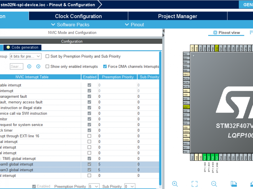
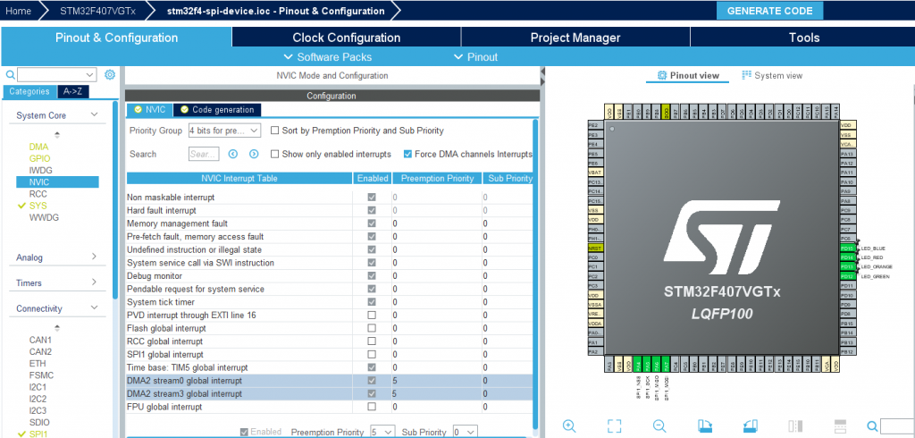
- Select System Core -> NVIC
- NVIC tab
- Change the preemption priority of “DMA2 stream0 global interrupt” and “DMA2 stream2 global interrupt” to 5 - This is required so that we can call FreeRTOS system functions from inside the interrupt handler. By default the system interrupts have the highest possible priority (0), but in order to call FreeRTOS functions (to wake a thread for example) the priority must be lower than the FreeRTOS priority (which is defined in FreeRTOSConfig.h). See https://www.freertos.org/RTOS-Cortex-M3-M4.html
- Make sure that the “priority group” is set to “4 bits for pre-emption priority”. FreeRTOS recommends having all priority bits allocated to pre-emption, rather than sun-priorities. See https://www.freertos.org/RTOS-Cortex-M3-M4.html
- Code generation tab
- Deselect “Generate IRQ handler” for “System service call via SWI instruction”, “Pendable request for system service” and “System tick timer” - FreeRTOS defines its own handlers for these, and if CubeMX also generates handler functions then the linker will throw an error about multiple definitions.
- NVIC tab
- In the pinout diagram
- Click on any pins you would like to use as outputs (LED indicator for example) and select
GPIO_Output. I set up the 4 user LEDs on teh discovery board (PD12-PD15) - Under System Core -> GPIO select the pin and change the “User Label” to something useful, eg.
LED_GREEN.
- Click on any pins you would like to use as outputs (LED indicator for example) and select
Clock configuration tab
- Change HCLK (MHz) to whatever you like. This example project used 100MHz. This is not particularly important unless you intend to run the SPI bus at very high speeds.
Project manager tab
- In the project tab on the left:
- enter a project name. eg. stm32f4-spi-device
- choose a location on disk to save the project
- Application structure. Choose either basic or advanced. Advanced creates a few additional directories to separate the auto-generated code from the user code. I used basic for this project. Note. Once you generate the code the first time you can’t change this again without restarting the project.
- Toolchain / IDE: Makefile
- In the code generator tab on the left:
- Optionally select “Generate peripheral initialization as a pair of .c/.h files per peripheral
- I like this as it separates the code into smaller logical files. But, this is optional.
- Optionally select “Generate peripheral initialization as a pair of .c/.h files per peripheral
Click on “Generate Code” to finish.
Manually fix up the project and add FreeRTOS
FreeRTOS
CubeMX has the option of adding FreeRTOS to your project for you (under middlware->FREERTOS). However, it wraps it in another os abstraction layer with very little documentation - I prefer to just use FreeRTOS directly. To do this:
- Download FreeRTOS from https://www.freertos.org/
- Copy the FreeRTOS/source directory to the project directory under
Drivers- You only need the list.c, tasks.c, queue.c and timers.c files. You can delete the others if you wish.
- In the
portabledirectory, you only need to keep theMemMangandGCC_ARM_MCF4directories - you can delete all the others.
- Create a
FreeRTOSConfig.hfile in your/incdirectory. Use the one in the linked repository as a starting point.
Makefile
Next we need to add the FreeRTOS sources to the makefile. Under the C_SOURCES section, add the FreeRTOS source files, as well as a comms.c file which we’ll add later
Drivers/FreeRTOS/Source/list.c \
Drivers/FreeRTOS/Source/tasks.c \
Drivers/FreeRTOS/Source/queue.c \
Drivers/FreeRTOS/Source/timers.c \
Drivers/FreeRTOS/Source/portable/GCC/ARM_CM4F/port.c \
Drivers/FreeRTOS/Source/portable/MemMang/heap_4.c \
Src/comms.c
Under the C_INCLUDES add the FreeRTOS include directories
-IDrivers/FreeRTOS/Source/include \
-IDrivers/FreeRTOS/Source/Portable/GCC/ARM_CM4F
Finally, the Makefile generated by CubeMX has a clean section, but, even though it is a windows tool, it uses the linux rm command. So, change that to:
clean:
	rmdir /Q /S $(BUILD_DIR)
The code
Protocol
The SPI protocol is just the physical layer, so we need a communication protocol to sit on top so that the controller and device can communicate. For the pupose of this post we will just use a very simple example. The device will have a data buffer which stores a string. The controller can either read this string, or write a new string to it to overwrite it. The protocol to allow this will be:
- All communication is initiated by the controller (always the case for SPI)
- The controller sends a “command packet” which consists of 2 bytes.
- Byte 1 is the read/write byte. 1 signifies the controller will write data to the device, 0 indicates it will read data
- Byte 2 is the number of bytes the controller will write. This is ignored if the controller is doing a read.
- At the same time, the device sends back its “status byte” followed by the number of bytes in its memory that it would send back to the controller if the controller is doing a read. This is ignored if the controller is doing a write.
- Then, the controller starts the “data packet”
- If it is a controller write, then the controller does an SPI transfer to send the data (the device already knows how many bytes to expect since it was specified in the control packet).
- If it is a controller read, then the controller checks the 2nd byte sent to it in the control packet to get the number of characters the device wants to send. The controller then does an SPI transfer to read this many bytes.
Implementation
The full source code is available here: https://github.com/mcgodfrey/stm32f4-spi-device
Note: this is just example code to get the SPI up and running. There is no error checking, status checks, buffer overrun checks, etc. These would all need to be added before using in a real application.
main.c
main.c is automatically generated by CubeMX with initialisation calls for the GPIO/DMA/SPI peripherals, as well as the system clock. All that we need to do is set up the FreeRTOS scheduler and create a couple of tasks. First there is a dummy “worker thread” called blinky, which just flashes an LED. This would be the main thread which actually performs the work. The second thread is the communication thread which we’ll go into in more detail below. An abridged version of the code is included below with some of the MX generated code along with my additions (see the link above for the full code). Remember to only add code between the /*USER CODE BEGIN …*/ and /*USER CODE END …*/ blocks.
/* main.c*/

/* USER CODE BEGIN PD */
#define PRIORITY_BLINKY_TASK  ( tskIDLE_PRIORITY + 1UL )
#define PRIORITY_COMMS_TASK  ( tskIDLE_PRIORITY + 2UL )
/* USER CODE END PD */
...

int main(void){
  // auto-generated init by CubeMX (compressed for readability here)
  HAL_Init();
  SystemClock_Config();
  MX_GPIO_Init();
  MX_DMA_Init();
  MX_SPI1_Init();
...

  /* USER CODE BEGIN 2 */
  xTaskCreate(blinky_task, "blinky", 100, NULL, PRIORITY_BLINKY_TASK, (TaskHandle_t *)NULL);
  xTaskCreate(comms_handler_task, "comms", 100, NULL, PRIORITY_COMMS_TASK, (TaskHandle_t *)NULL);
  vTaskStartScheduler()
  /* USER CODE END 2 */
...

  while(1){

  }
)
Note:
- The priority of the comms task is higher than the “blinky” task. This means that it can respond quickly to communications, but should yield as quickly as possible to avoid blocking the main thread.
- A lot of the auto-generated code has been excluded, as well as the
blinky_task()implementation - see the link above for the full code. - The auto-generated while() loop is empty, since the call to
vTaskStartScheduler()blocks, so it never makes it to the main while loop.
comms.[hc]
The actual comms interface is implemented in comms.[hc]. This task is structured as a main while loop which sets up the SPI DMA transfer and then sleeps, yielding control back to the main thread. It only wakes briefly when notified by the SPI transfer complete interrupt, before going back to sleep again. It uses the FreeRTOS Task Notification API (https://www.freertos.org/RTOS-task-notification-API.html) which are basically a lightweight binary semaphore implementation. Ie. the loop “takes” the notification and will sleep until another function (the SPI transfer complete interrupt handler in our case) “gives” it back a notification.
The code below should be fairly self explanitory. After defining the tx/rx/stored-message buffers, the main comms loop works as follows:
- Puts the status byte and message length into the start of the tx buffer
- Starts a 2-byte DMA transfer for the command packet
- “takes” the notification and goes to sleep
- Once the transfer is complete, the interrupt handler callback (
HAL_SPI_TxRxCpltCallback) “gives” it a notification which wakes it up - It inspects the command and decides whether to write its stored message (ie. put it in the tx buffer) or read in a new message from the controller (ie. save the rx buffer into the stored message buffer).
- It then sets up a second DMA transfer of the correct length
- And “takes” the notification again.
- When this second transfer is complete, the interrupt callback again “gives” it the notification back and it loops back to the beginning.
/* comms.c */
#define BUFFER_LEN 32
...

uint8_t stored_message[BUFFER_LEN] = "initial string"
uint8_t comms_tx_buffer[BUFFER_LEN]
uint8_t comms_rx_buffer[BUFFER_LEN]

/* main comms thread task */
void comms_task(void *pvParameters){
  // save a reference to this thread, so that the interrupt handler can wake it up
  comms_task_handle = xTaskGetCurrentTaskHandle();
  ...

  while(1){
    comms_tx_buffer[0] = comms_status;
    comms_tx_buffer[1] = strlen(stored_message);
    // start an SPI DMA transfer of 2 bytes
    HAL_SPI_TransmitReceive_DMA(&hspi1, comms_tx_buffer, comms_rx_buffer, 2);
    // Sleep thread until the spi xfer is complete
    ulTaskNotifyTake(1, portMAX_DELAY);

    uint8_t controller_write = comms_rx_buffer[1];
    if(controller_write){
      // controller write to this device
      uint8_t nbytes = comms_rx_buffer[1];  // Note: should check that this is less than BUFFER_LEN
      memset(comms_rx_buffer, 0, BUFFER_LEN);
      memset(comms_tx_buffer, 0, BUFFER_LEN);
      HAL_SPI_TransmitReceive_DMA(&hspi1, comms_tx_buffer, comms_rx_buffer, nbytes);
      // sleep until SPI transfer is complete
      ulTaskNotifyTake(1, portMAX_DELAY);
      strncpy(stored_message, comms_rx_buffer, nbytes);
    }else{
      // controller read from this device
      memset(comms_tx_buffer, 0, BUFFER_LEN);
      memset(comms_rx_buffer, 0, BUFFER_LEN);
      // copy the stored message into the tx buffer to send to the controller
      strcpy(comms_tx_buffer, stored_message);
      HAL_SPI_TransmitReceive_DMA(&hspi1, comms_tx_buffer, comms_rx_buffer, strlen(stored_message));
      // sleep until the SPI transfer is complete
      ulTaskNotifyTake(1, portMAX_DELAY);
    }
  }
}

/* Callback when the DMA transfer is complete. Notifies the comms thread to wake it up*/
void HAL_SPI_TxRxCpltCallback(SPI_HandleTypeDef *hspi){
  BaseType_t higherPriorityTaskWoken = 0;
  vTaskNotifyGiveFromISR(comms_task_handle, &higherPriorityTaskWoken);
  portYIELD_FROM_ISR(higherPriorityTaskWoken);
}
Notes:
- The callback name,
HAL_SPI_TxRxCpltCallback, must match exactly - this is required by FreeRTOS in order to call the callback. Alternatively, this code could probably go directly in the ISR, which is defined instm32f4xx_it.cin eitherDMA2_Stream0_IRQHandler()orDMA2_Stream2_IRQHandler(). But, I think putting it in the callback is cleaner. - There is no error handling at the moment.
- The status in hal_status should be checked before going to sleep, to make sure the SPI/DMA is ready
- The thread probably shouldn’t sleep forever (
portMAX_DELAY). Instead, it should probably wake periodically to make sure there are no problems.
- The total time that this thread is awake is very small - it just wakes for long enough to read/write the new data into the tx/rx buffers, trigger a new transfer and then go back to sleep. In a real application, handling the commands from the controller might involve manipulating some internal state, or triggering actions in the main thread, etc. But, the idea is similar, and should always return as quickly as possible to avoid blocking the main thread.
Testing
To test the code, there is a python script in the repository called stm32_spi_test.py. To run it, connect the SPI lines and run the script as python3 stm32_spi_test.py.
The script does an initial read of the device string, then writes to it and reads the result back. Output below:
$ python3 controller.py
-- Reading from device
   device wants to send 14 bytes
   response = "initial string"
-- Writing to device
   sending "this is a write test"
-- Reading from device
   device wants to send 20 bytes
   response = "this is a write test"
Conclusion
The basic setup is working, showing how to set up an SPI DMA transfer in device-mode to listen for data from the bus controller. It works well with FreeRTOS, once the priority on the DMA servicing interrupt is set lower than the FreeRTOS priority. There are a number of improvements to be made before this would be robust enough to include in a real application:
- Error checking
- Currently the status byte is never inspected. Both the controller and device should check the status after each transfer and default to some defined state if there is a problem.
- CRC
- There should be a CRC byte appended to the end of each message to check for any transmission errors. This would also require a robust way for the device or controller to signal to the other in case of a CRC mismatch, and to resend the data, or move to some other defined state. The STM32 devices support automatic CRC generation/checks but I haven’t tested this yet.
- Timing edge cases
- What happens if the controller initiates the <data packet> transfer before the device is ready (before it has called the DMA transfer start)? This could happen for example if the controller is too fast, or if the device takes some time to read a certain register. Or if another higher priority interrupt delays it temporarily. There should be a mechanism for the controller to poll if the device is ready. The controller probably reads all 0 if the device doesn’t respond - so, the status byte would be 0 which indicates busy. The controller could then retry the transfer.