This post is going to cover my first impressions of using Autodesk’s Fusion 360 CAD program from the point of view of someone who is completely new to CAD. Several months ago I bought myself a 3D printer (a Printrbot Simple – hopefully I’ll do a post on this in the future) partly as an impulse buy, partly because I’ve always been curious about them, and partly as an excuse/reason to learn how to use CAD to design parts.
As a complete beginner, I didn’t want to fork out cash for software so I searched around for some free options to get started. There were 3 which stood out:
- Autodesk Fusion 360
- Autodesk have a huge number of different programs and I can’t pretend to know the differences between them all. As far as I can tell, for my basic CAD requirements they all do mostly the same thing. Fusion 360 however is free for students and hobbyists so that was the obvious choice.
- It is Windows only and a large installation, but it went very smoothly, as did the activation with the free hobbyist license. It is a “cloud based” software so all your designs are saved on their servers and apparently it is designed for sharing and collaborating which I haven’t tested. So far the cloud based approach seems well implemented and unobtrusive and everything is always kept up to date.
- Onshape
- This is a full CAD tool which runs entirely in the browser and marketed as a modern, run-anywhere alternative to more traditional tools such as Autodesk. Being browser based is very convenient sometimes, you can log in to the website from any computer and start working immediately – no need to download or install anything.
- Seems to be very similar to Fusion functionality- and look-and-feel wise. Being new to CAD, I’m not sure if this is what all CAD packages look like, but there are a lot of similarities. If you know one, it’ll be pretty easy to find your way around the other.
- I tested onshape initially before Fusion, but for some reason it annoyed me a bit. I’m not sure if it was that it was in-browser, or it felt slightly more sluggish or buggy, or what. But something about it didn’t feel as nice or polished which is why I have focussed mainly on Fusion.
- Openscad
- Free and Open source. This seems to be quite popular in the 3D printing community because it is free and open, small and simple to use (for simple designs). It runs on Windows and Linux (and presumably mac?)
- This is a text based tool where shapes are defined in a text file from basic building blocks. It is then compiled and the 3D model generated and shown in the integrated viewer.
- This is a very basic tool and in a completely different category compared to the other two in this list. It barely even makes sense to compare them. But it does seem good for what it is.
Overview
This will be an overview of my learning process and will be a combination of comments on CAD software in general, and Fusion 360 in particular.
My very first attempts to get started without reading any manuals or tutorials did not turn out as well as hoped. I was expecting to just start drawing some cubes and cylinders, moving them around and joining them together. It turns out this isn’t how it works. So I turned to some tutorials which are very useful and built in to the help menu. I started with the lamp tutorial which creates a new project and takes you through the whole process of designing the part. You quickly pick up the basic workflow which can be summarised as:
- Sketch 2D shape
- Extrude/revolve/apply some other operation
- repeat
This is very different to my initial expectations of just joining up basic shapes and at first it seemed very restrictive. But it turns out that after a small amount of practice with these 2 basic steps you can quickly make some very complex parts. There are many more complex steps beyond sketch->extrude, but with these basic building blocks you can do quite a lot.
Sketching
All of the magic happens in the sketch. This is where you draw a 2D shape with can then later be extruded/revolved/whatever into 3D. The sketch plane can be placed in any direction, or attached to another surface so that everything is aligned. It is quite easy to sketch shapes with all the basics objects including lines, rectangles, circles, splines, etc. However the real power comes from the ability to add dimensions and other constraints to the sketch to parameterise it.
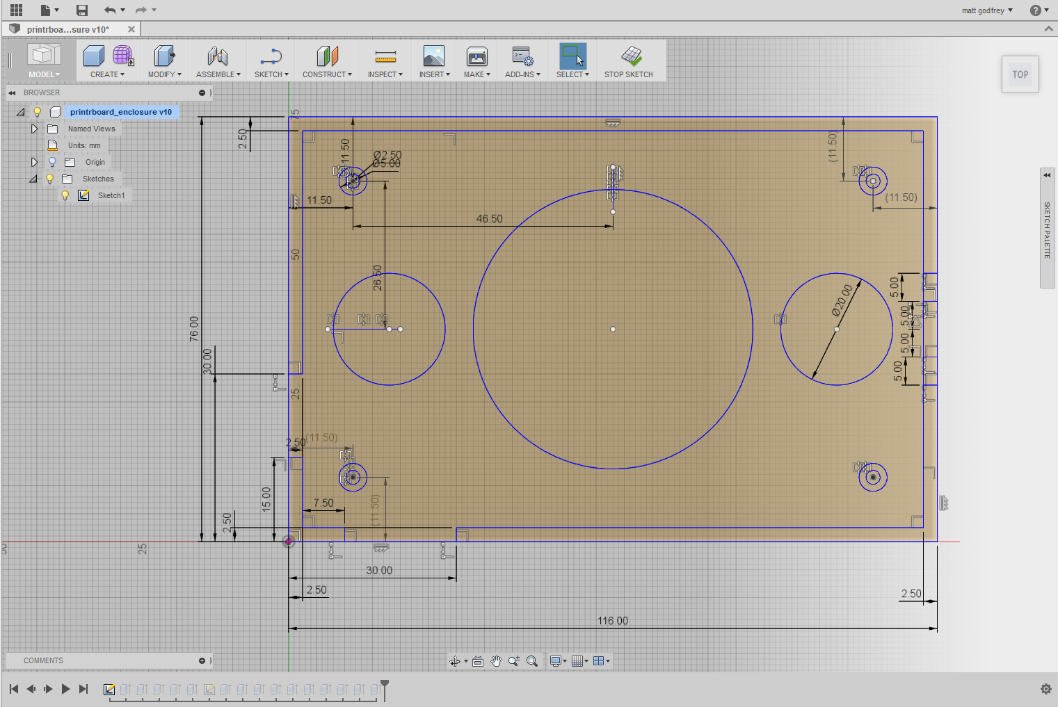
Dimensions are fairly straightforward and can be added to any objects, lines circles, etc. They can be changed later and the objects will resize automatically as expected. Nothing unexpected here.
Add in some constraints though and things get more interesting. Constraints are additional information you can add to the sketch, such as requiring that 2 lines are perpendicular, or that a line is tangent to a circle. Fusion is pretty good at guessing when you want some basic ones, such as perpendicular lines, but you can always add them later as needed. When your sketch has constraints, changing one part of it will cause the rest of the sketch to update automatically to ensure that all of the constraints are met.
This power does come with quite a bit of complexity and things can get confusing pretty quickly. Forgetting or assuming certain constraints can lead to unwanted problems when you resize parts, if you forget to explicitly set 2 lines as parallel for example. If you have something relatively complex the screen can get cluttered with all the constraints and it can be difficult to see what is missing. Several different constraints can be used to achieve the same goal – for example, a square can specify 2 right angle corners, it can specify opposite sides are parallel, or that adjacent sides are perpendicular. Mixing and matching all these different options can make it tricky to see if you have fully constrained the design or not.
Extruding and 3D
Once the sketch is complete, you can start extruding and building up in 3d. In addition to extruding, you can revolve sketch objects around an axis, or sweep it along a line, plus more. New sketches can be started on faces (eg. sketch cut-outs in a sidewall). A full history of every operation is kept and you can go back and modify previous steps (eg. increase the base thickness) and if everything is set up correctly, then everything else should automatically update. You can go back and modify sketches, and any parts which were built from that sketch are updated.
Designing a simple part
An example of a simple part I designed is a mount to hold the controller board and an additional temperature controller board for my Printrbot. Normally this is mounted underneath the printer body, but I have enclosed my printer in a heated box up to reduce warping while printing. Keeping the board inside a heated box seemed like a bad idea, so it needed somewhere to live outside.
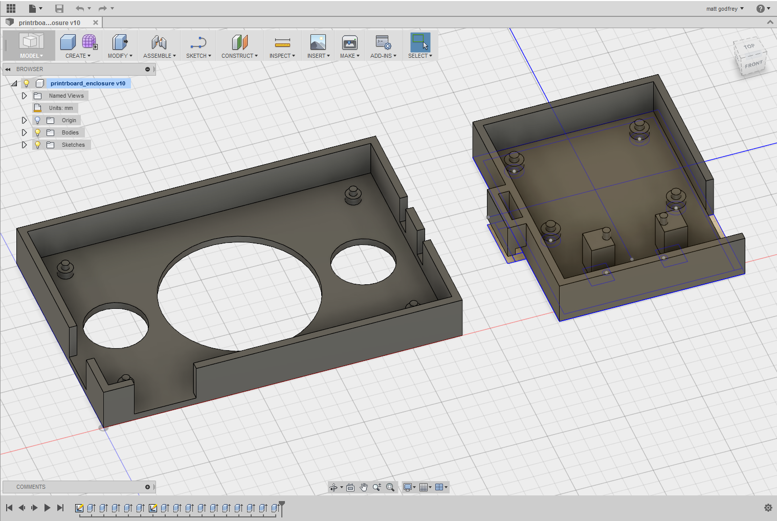
The final model and the actual printed part are shown above. The design is fairly simple, and roughly based on some similar parts I found on Thingiverse, but none of them really fit the bill exactly. I also wanted to design an additional mount for the temperature controller and switch which would attach to the main part. Ideally I would have designed a single part to hold both, but I am constrained by the 150x150x150mm build volume of the Printrbot.
This design is fairly simple and everything is extruded from a single sketch. I started with the main board, defining the outline of the base, the walls around the edge (with cut-outs for connectors and wires) and the mounting posts (I decided to use posts which stick through the mounting holes on the board, rather than using screws). I also added some circular cut-outs in the middle of the base to reduce the printing time and material usage. Finally, the locking mechanism for the second board was added to the right. Leaving the sketch, all the areas were then selected and extruded.
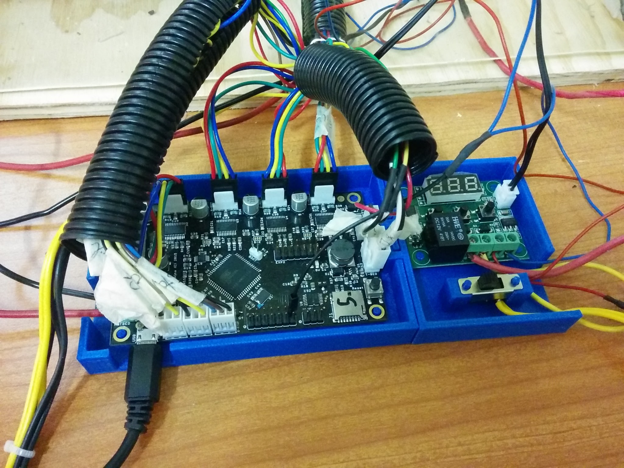
The second board was created with exactly the same process. The locking mechanism was a bit tricky and required 2 prints to get right. The issue was with printing tolerances, rather than with the design process. In the end I needed to build in larger tolerances to get everything to fit together nicely.
A few things to note about the design. Wherever possible I exploit symmetry and mirror parts. For example the 4 mounting posts are all mirrored from a single circle. This has a couple of advantages – changing the size of one circle automatically updates the others, to adjust positioning you only need to move one of the circles and they all update. The locking mechanism was also fairly heavily parameterised which made it simple to make adjustments when I needed to adjust it due to the tolerances in the printer.
Once everything is designed, you simply right click on the bodies and select export as .stl which can then be sent directly to the printer software (I use cura) for printing.
Conclusions
Overall, I am very very impressed with Fusion 360, especially considering the cost (free!). It is quite easy to pick up the basics and get to the point where you can design useful parts – the built in tutorials are very helpful in this regard. As someone with no prior CAD experience I would say it was less than 5 hours between installation to printing my first custom part which isn’t too bad I don’t think.
There are plenty more advanced features which I haven’t even started to master yet – in particular creating freeform or arbitrary shapes is very difficult for me at the moment. There are also a lot of additional features including building full assemblies and defining relationships and joints between parts, relative motion and simulation, fancy rendering and texturing as well as many different export options for fabrication.
I plan to continue using Fusion and learn how to use more of its features. At the same time I am starting to have another look at Onshape so that I can make a proper comparison between them, rather than just a first impression.

2 comments