
This post is part of my series on building a kinetic sculpture with the Mojo FPGA development board. (Part1 Part2)
Back at uni I did a course on digital logic design (COMP3222 for anyone interested) and really enjoyed it – it was one of my favourite classes. But for some reason I never followed up on it or did any more. I think part of the reason is the relatively large cost and complexity of FPGAs compared with microcontrollers. Anyone can buy an Arduino for a few dollars and get started pretty much immediately. Not so for an FPGA. In order to pick up where I left of at uni I’ve ordered myself a mojo board and plan to start getting back into some FPGA development.
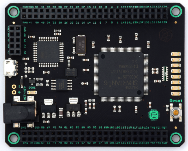
I chose the mojo board after a quick search so I am by no means recommending it (not yet anyway). I figure I don’t really know what I’m looking for so it’s as good a place to start as any. There are a lot of tutorials on the website and some example code which I took as a good sign. I’ll find out when it arrives (which should be a couple of weeks).
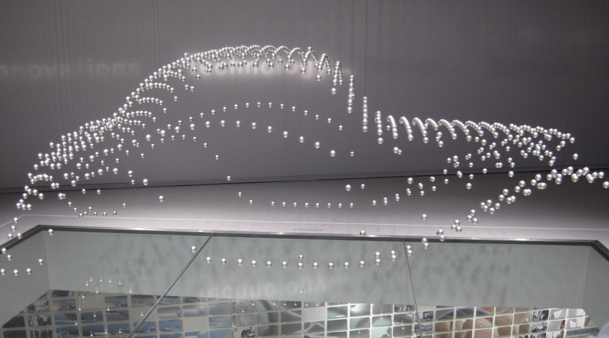
To get started I need a project, so my idea is to make a smaller scale version of the kinetic sculpture I saw at the BMW museum in Munich this time last year (video here). It consists of a number of weights suspended by strings which can independently be moved up and down to create some cool looking moving sculptures. I figure this should be a relatively simple task for an FPGA and takes advantage of the very high IO count (the mojo has 84 IO pins which should allow a 9×9 grid). The hard part will be designing the actual sculptures and movements once the build is complete. I have considered building something similar to this in the past but always ran up against problems with limited pin counts on microcontrollers, requiring many of them to divide up the work which always put it in the too-hard basket.

The basic design I have in my head is to have the string for each ball attached to a servo motor and geared to give the correct travel. Each servo will be controlled by a dedicated pin by the FPGA. I have never used servo motors before, but my understanding is that they require power and a single modified PWM signal to set the position. This is perfect for the FPGA as I should be able to directly drive the signal line for each servo from the FPGA without needing to worry about drivers or isolation.
In terms of code structure, the mojo contains an onboard AVR microcontroller which handles initialisation of the FPGA and can then be used for other tasks once this is complete. My rough plan is to have the AVR calculate the required positions of all the motors and send these to the FPGA. The FPGA will then just be responsible for converting these positions into PWM signals required by the servos and outputting them. So in terms of the FPGA, it will involve some counters/timing, IO, memory and serial comms which will hopefully be enough to make this an interesting first project.
That’s all for now. I’ll be back with an update when I get some code written and the board arrives.
Update (9/1/2013): Project code is now up on github. This is very much the development code (read. it doesn’t work) and will be updated as I go.
One comment