
I have finally finished my temperature monitor and logging module, originally designed to monitor beer temperature as it is fermenting (beer, fridge and ambient temperatures). It is an Arduino-based device which measures and displays temperatures from multiple attached temperature probes and logs them to an SD card. This is an old project from last year sometime which has been sitting 95% complete, just waiting on an enclosure and some finishing touches to the code.
I posted a separate post about the enclosure design and 3D print, read it here.
Overview
This project was actually slightly more involved that I originally thought it would be. It uses quite a few devices (temperature probes, LCD, SD card, Real-time Clock module and some pushbuttons) and requires some slightly more complicated code than usual since it has to provide a nice responsive UI as well as the background logging functionality.
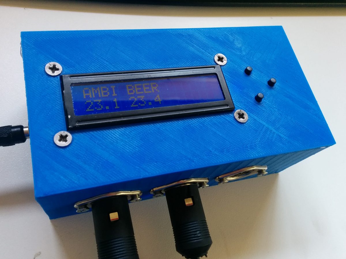
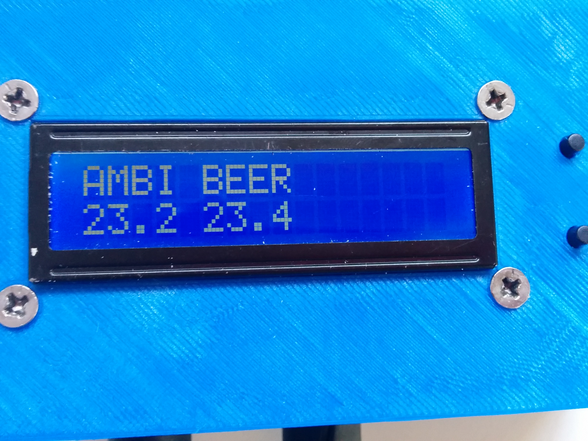
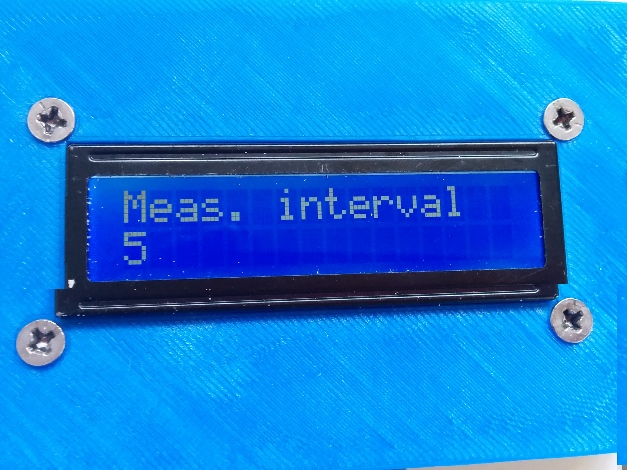
The UI menu system is controlled via 3 pushbuttons (up, down and select). The main screen is the temperature display, and the buttons allow you to change settings such as the sampling rate and to enable/disable the SD logging.
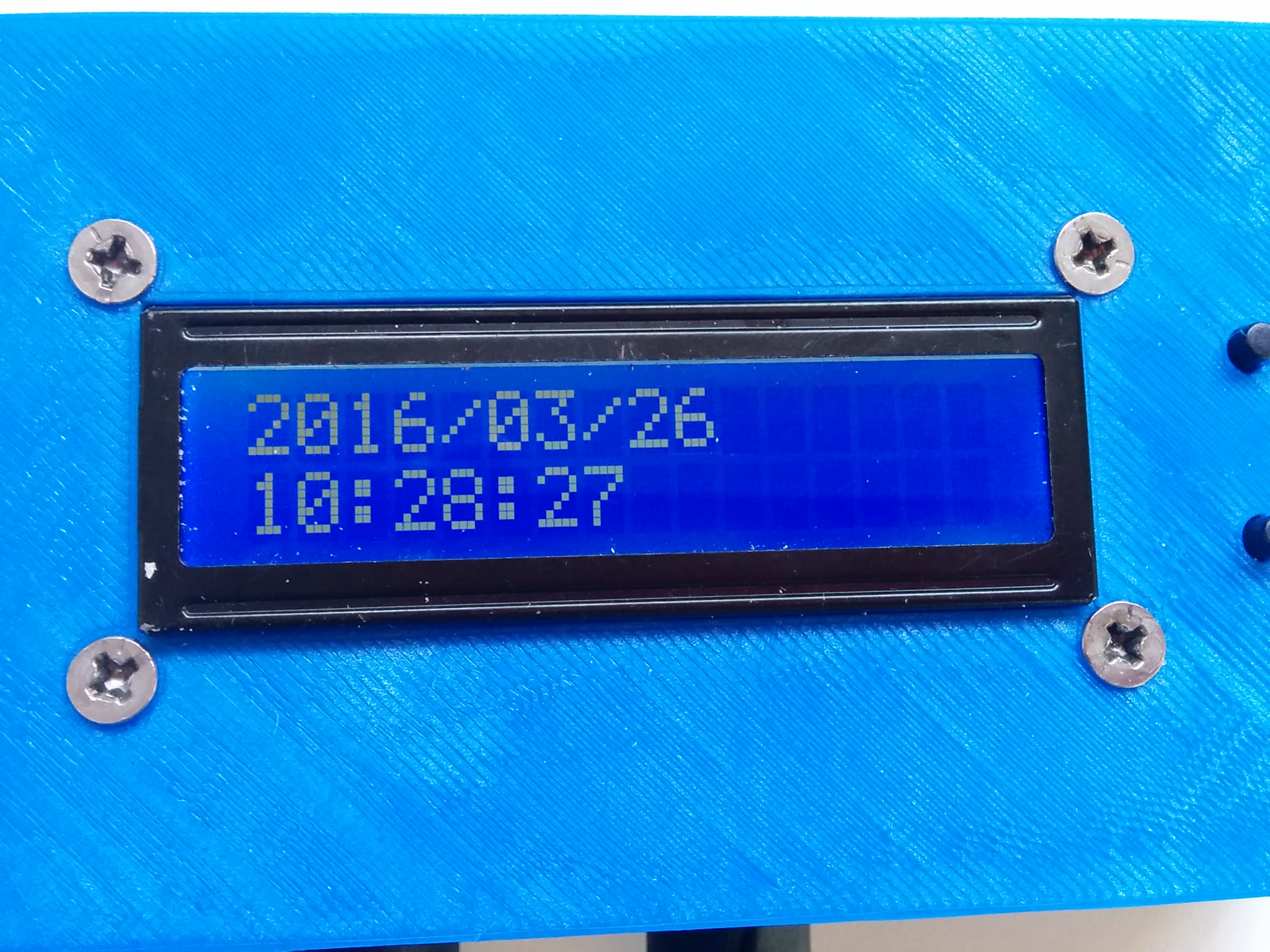
In the background behind the menu, the temperature is being logged and saved at whatever sampling rate is selected. The RTC provides accurate timestamps for each of the measurements which are saved to the log file. I will quickly go through the physical build and then go into some details about the code.
The Build
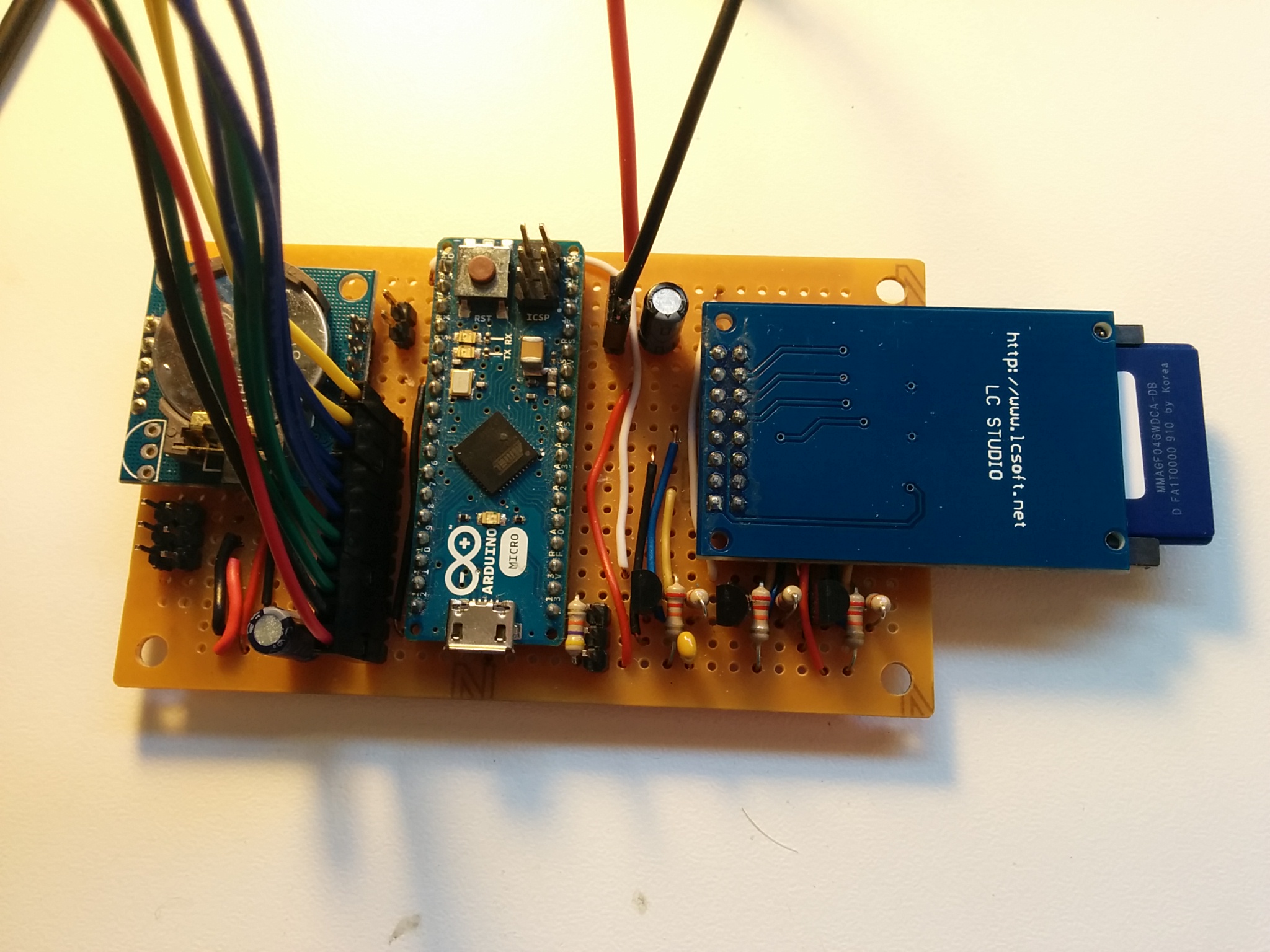
Most of the electronics (Arduino, RTC, SD module, level shifter, temperature probe connectors and power input) sit on a single breadboard ~50x90mm with the SD card module hanging off the edge. The 11 pin connector goes to the LCD and pushbuttons. Important to note on this are the filter caps (100uF) on the power rails and input, and the MOSFET/resistor level shifter for converting between 5V and 3V3 for the SD card.
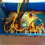
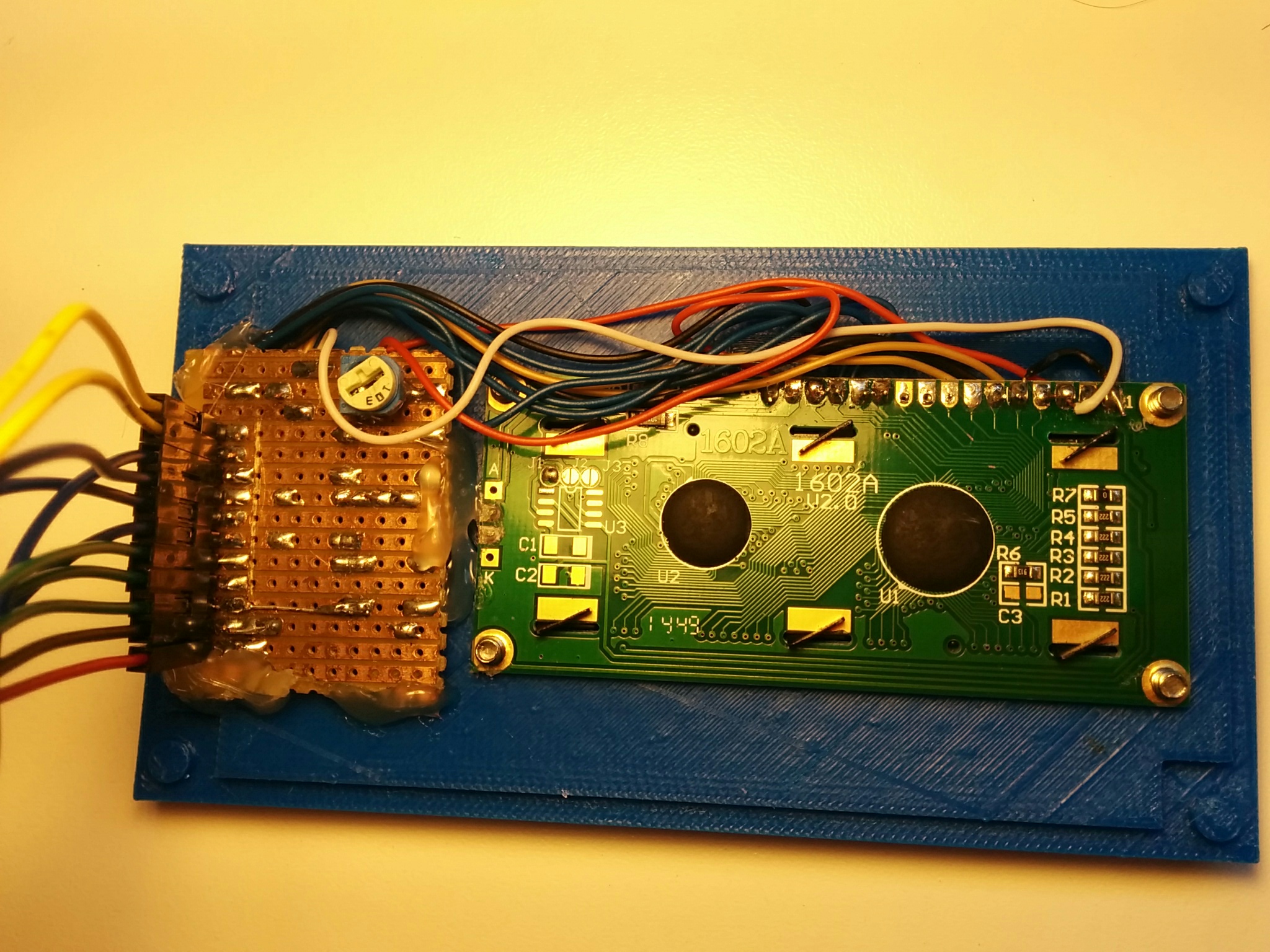
This board fits into the base of a 3D printed enclosure (see this post for details). There is a slot for the SD card to be inserted and holes for mounting the DC power jack and temperature sensor connectors. The lid of the box holds the LCD and pushbuttons.
And the completed enclosure!

Code
The code for this project is on my github page here.
There are two distinct functions that this code has to provide – temperature logging with accurate timing, and a responsive UI and temperature display. Temperature sampling and logging is achieved with an interval timer which triggers a measurement, and the UI is implemented as a state machine with a separate state for each menu screen. In the main loop the code first checks the timer to trigger temperature measurements, and then processes any button presses to determine the new state for the UI and updates the display.
Temperature Probes
The temperature probes are 1-wire probes similar to these (although I bought mine for significantly less from eBay), built around the Maxim DS18B20 digital temperature sensors (datasheet). The 1-wire protocol is very neat, requiring just 1 wire for both power and data (it still needs a ground wire though), although they can also be operated with separate power and data lines which speeds up the operation. The other really interesting point is that every device has a unique 64-bit address which is hard coded at the factory, meaning that each individual probe can be uniquely identified by the code.
All the devices share a common data line, so probes can be connected and disconnected into any of the connectors and the code will know immediately which ones are connected. This also means that I can assign meaningful names to each of the probes in the log file, eg. BEER and AMBIENT and there can be no confusion over which probe is measuring which temperature.
Timers
There are a couple of ways to implement an interval timer – using interrupts or polling the time in a loop. I’ve decided to go for the latter because it’s a little simpler and because I don’t mind if the sampling time is not absolutely accurate. I based the code on the SimpleTimer Arduino library, but simplified it by removing all the features I wouldn’t need. It works by calling the timer’s run() function at the start of the main loop. This checks if enough time has elapsed since the timer was started and then calls the registered callback function. See the code snippet below.
https://gist.github.com/mcgodfrey/9f7d871b1ce7590b98a6
The main measurement interval timer (called measTimer in my code) calls the measure_temps() function when it expires. The temperature sensors that I am using actually take some time to take a reading (up to 750ms at the highest resolution) which causes the UI to lag and become unresponsive if we wait for the reading to complete. So instead, the measure_temps() function just triggers a measurement to begin, sets up a second timer (called conversionTimer) and then returns so that the main loop can continue. When this second timer expires it calls conversion_complete() which simply reads from each of the probes, updates the display and logs the new reading. The code snippet below (some code omitted for brevity here – the full code is available on github) shows how this works.
https://gist.github.com/mcgodfrey/041906cca1e69b1af7e7
I have one final timer (display_timeout) which returns to the temperature display state when it expires (default 10s). This just ensures that the temperature display screen is always showing when it is left alone. The timer is started whenever there is a button press.
Buttons
Button presses are handled by a modified version of the Switch library (which now seems to be depreciated, linking you to the Button library). Button presses need to be debounced to prevent each press registering multiple presses in the software. This is achieved in the code by waiting a fixed time (50ms in my code) after a press is first detected before the press is registered. Each button gets it’s own switch object which has a poll() function. This is called at the top of the main loop, similar to the timer polling, and returns true once a button press has been registered and debounced.
https://gist.github.com/mcgodfrey/42d444ad6209b29e5b7d
Logging
RTC
The RTC is basically a 32.768kHz watch crystal and a chip with a counter which keeps track of the time. It has a battery so that it maintains the time when the power is removed, and it talks over I2C to the Arduino, returning the current time when requested. There is an Arduino library, RTCLib, which handles communication and provides a datetime class which can be used to format the time nicely. The module has to initialised once (There is a separate Arduino sketch in the project on github for this) and then it will remember the time from then on, even through power cycles and reprogramming the Arduino. Note that the accuracy of the crystal is not perfect and it could lose or gain ~15s per month, so the time may have to be reset periodically.
SD card
The SD card module was bought from eBay and is basically just a socket. SD cards actually have their own SPI interface and can therefore communicate directly with the Arduino. The only complication is that the SD is 3.3V and the Arduino is 5V, so I need to level shift the lines. This is relatively simple, requiring just one MOSFET per data line, as well as a separate pullup resistor for the 3V3 and 5V sides – see this application note for more details.
There is an official Arduino library (SD) for reading and writing to SD cards. It handles the communication with the card as well as the filesystem details (it handles FAT filesystems which means the card can be read directly by a computer). It is as simple as opening the file, writing the new data and closing the file again. There are a couple of complications to do with detecting whether a card is present (it takes several seconds), possible problems (according to some forum posts) with inserting a card after the Arduino is powered up, and the (very small) possibility of corrupting data if the card is removed during a write operation. In light of all this – I require that the SD card is inserted before the Arduino is powered up. If there isn’t one detected then the options for logging are not displayed, even if a card is added later. If the card is removed while the Arduino is trying to log to it, it results in an error and needs to be power cycled.
https://gist.github.com/mcgodfrey/e82c455c8468f97db1b4
Conclusion and improvements
The project is now at a usable stage where it runs as expected, logs temperatures and has a nice solid enclosure. There are still a few things I would like to improve though:
- If a new temperature probe is added you need to go in and modify the source code with it’s address and upload it to the Arduino. It would be nice if there was a method to name the probe from the menu and save it to EEPROM, rather than hard coding it.
- The enclosure doesn’t have a slot to access the USB port on the Arduino. This was a large oversight when designing the case and makes reprogramming and debugging difficult.
- I would like to automatically turn off the LCD backlight if there are no button presses for a certain amount of time. This is an unnecessary waste of power at the moment.
- There is no way to adjust the RTC time. I have a time display screen and I would like to be able to set the time from here using the pushbuttons. This would account for any drift over time. It might be necessary for example to update the time just before starting logging for a new brew.