

This will be a quick post about the design and 3D printing of a custom enclosure for a temperature logger (see full writeup here) – a project which has been sitting on my table 90% finished for about a year now. I always find the enclosure to be the most time consuming and least interesting part of any project. As such an unfortunately high number of them stall at this final stage. 3D printing a custom enclosure is a much more interesting and attractive alternative to my usual approach of attacking a jiffy box with a drill and hacksaw.
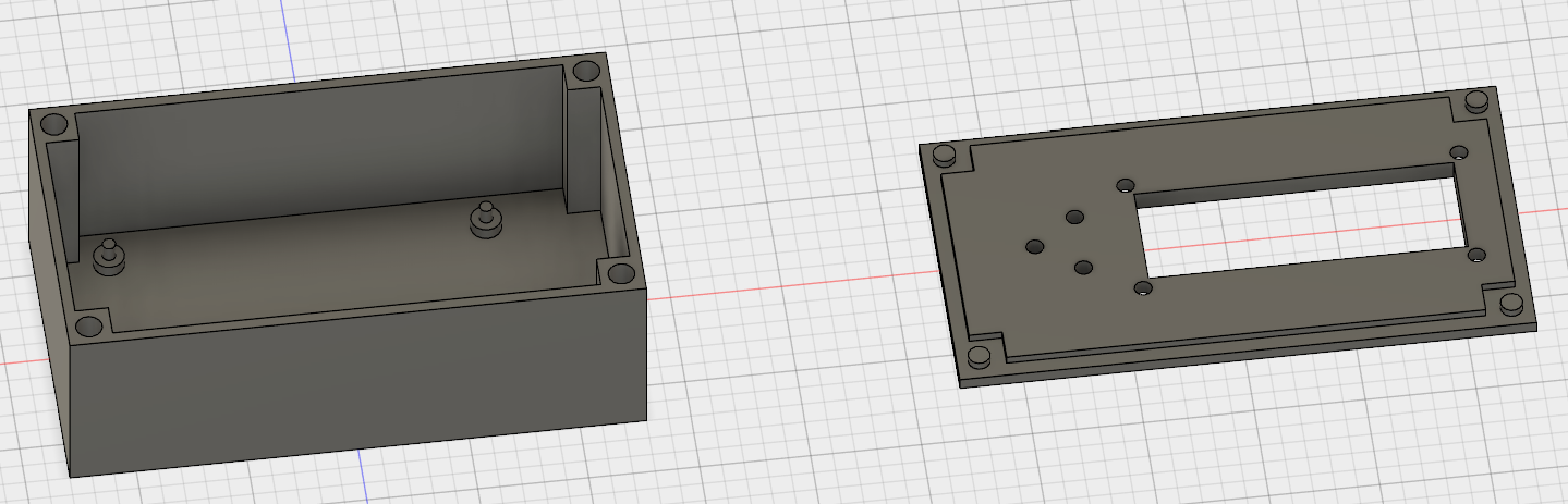
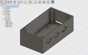
The box needs to hold a board roughly 90x50mm, have a slot for an SD card, 3 temperature probe input connectors, a DC jack power input, a 16×2 character LCD and 3 pushbuttons. The design was all done in Autodesk Fusion (see my previous post) and printed on my Printrbot 3D printer (see my previous post). There were several iterations and test prints along the way to check sizing and tolerances and to test out some different designs. The final design can be found on my Autodesk account here.
Design
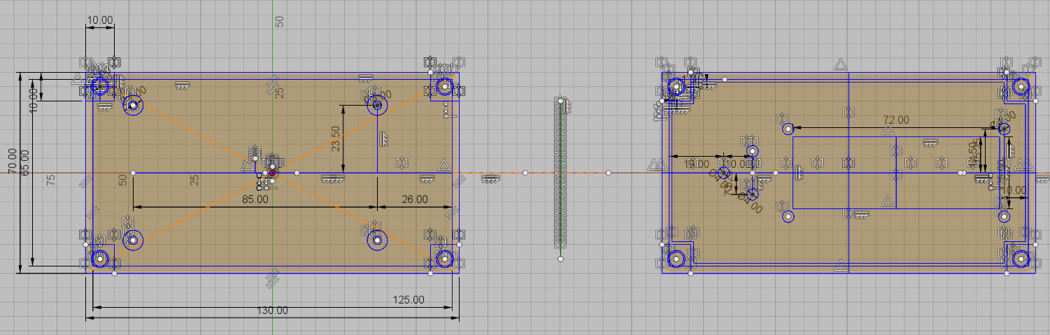
The first step is to create a sketch with the main outline, the walls, cutouts and standoffs on the base for the board to sit on. The lid is a mirror of the base (so that the sizing is exact) with its own cutouts for the pushbuttons and the LCD display. After the sketch is complete it is extruded to create the 3D shape and the cutouts are removed.
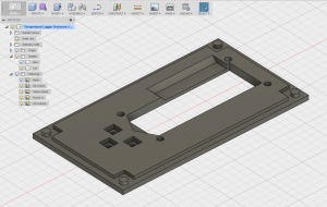
Note that the lid is designed to fit into the base with a raised central region which sits inside the walls of the base, and small cylinders which sit in holes in the base. This is so that there is a nice tight fit and the lid doesn’t move around. Also, it is not shown in the picture below but the 4 LCD mounting holes actually have countersunk heads (on the outside of the lid) so that the mounting screws can sit flush on the surface.
The next step is to include the cutouts in the sidewalls of the main box for the SD card, the temperature probes and the DC input jack. To do this I simply create 3 new sketches on each of the walls of the box, sketch the shapes and then extrude and cut them.
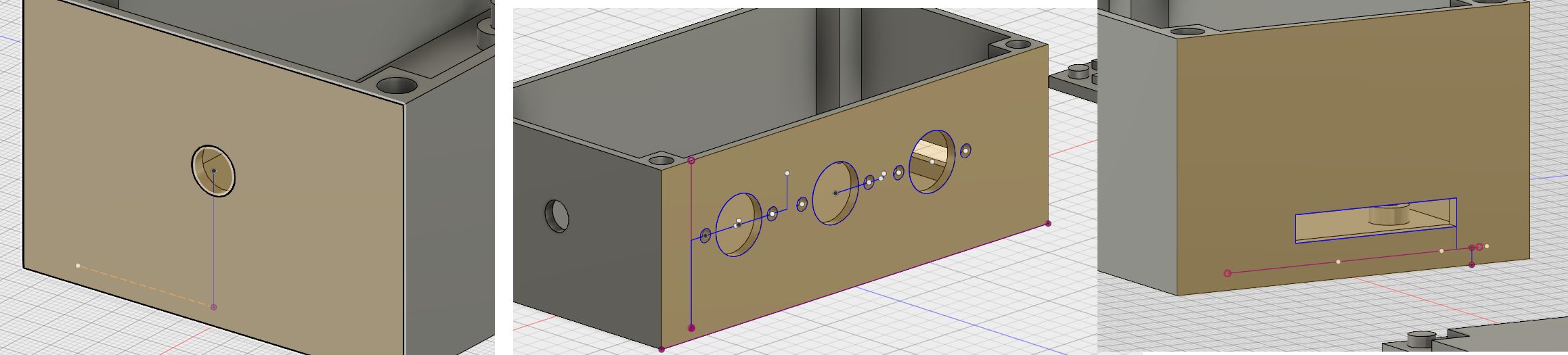
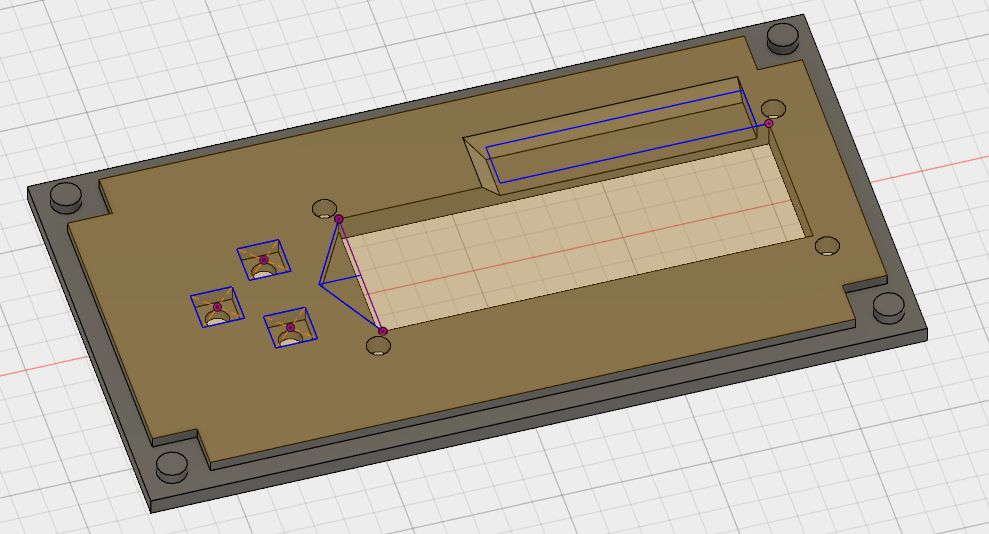
With the main box now completed, there is a final step required for the lid. I need to recess some areas for the pushbuttons and the LCD to fit, so I create one more sketch on the inside face of the lid.
The pushbuttons aren’t long enough to extend through the entire base, so I create some square cutouts to recess the base of the pushbuttons slightly – this will also help keep everything aligned. I also need a cutout at one end of the LCD where the backlight sticks out, and along one edge where I have soldered the connecting wires.
The final parts are then ready for printing!
Printing
The box and the lid were both printed on my Printrbot. I used ABS with a 20% infill, 0.4mm (single layer) wall thickness and support structures for the cutouts in the walls. There is no need for any raft or special care – since I’ve started using BuildTak and the heated enclosure there are no problems with warping or lifting. The total print time was ~3.5 hours for the box and 1.5 hours for the lid.
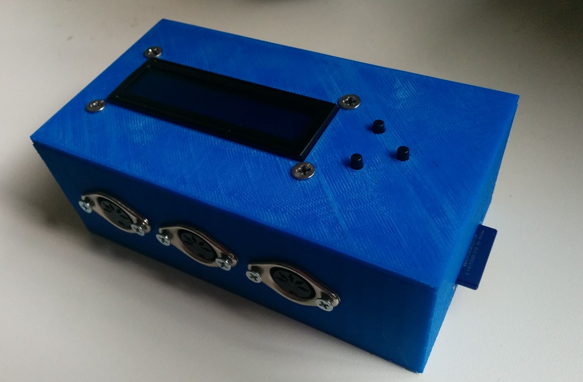
The board sits nicely on the standoffs and a dab of hot glue on each secures the board down nicely. The DC jack and temperature probes screw into the walls, as does the LCD on the lid. The pushbuttons are mounted on a separate board which doesn’t have any mounting holes on it (I could have redone it with some, but decided it wasn’t worth the effort). Si it is simply stuck to the lid with hot glue. I’ll be interested to see how this holds up long term.
And that’s about it! Very successful in the end I think. Minor improvements would be adding fillets to the corners to round them off a bit – I forgot about this until after I’d already printed the final version of the lid and didn’t think it was worth reprinting. Also designing the lid differently so that it clipped onto the box somehow or was screwed down, perhaps with a captive nut somewhere. At the moment it just sits there, although I might glue it down with a tiny dab of hot glue so that it can still be removed if I need to.
I’ll be putting up a post soon on the full temperature logger build which will show how everything fits together and how it all works. UPDATE (26/3/2016): The temperature logger is now working, see this post for a full writeup.
One comment